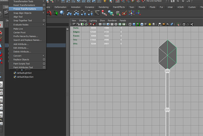
Make sure to freeze transforms and delete history on all geometry before we start.
Use joint tool with default options to add joint chain:
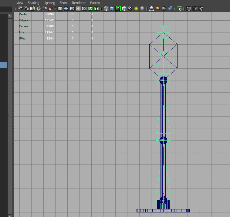
Rename joints from bottom to top: base_jnt, shoulder_jnt, elbow_jnt, wrist_jnt and wrist_end_jnt.
Parent geometry to the joints (base to base_jnt, base_pivot and lower_seg to shoulder_jnt, elbow_pivot and upper_seg to elbow_jnt, and wrist_pivot, claw_L, claw_R to wrist_jnt).
Create a nurbs circle with default options. Turn off polygons in the workspace show menu and hold down "v" while using the move tool to snap to point (in this case the shoulder_jnt). Rename the curve to shoulder_control and Modify->Freeze Transforms.
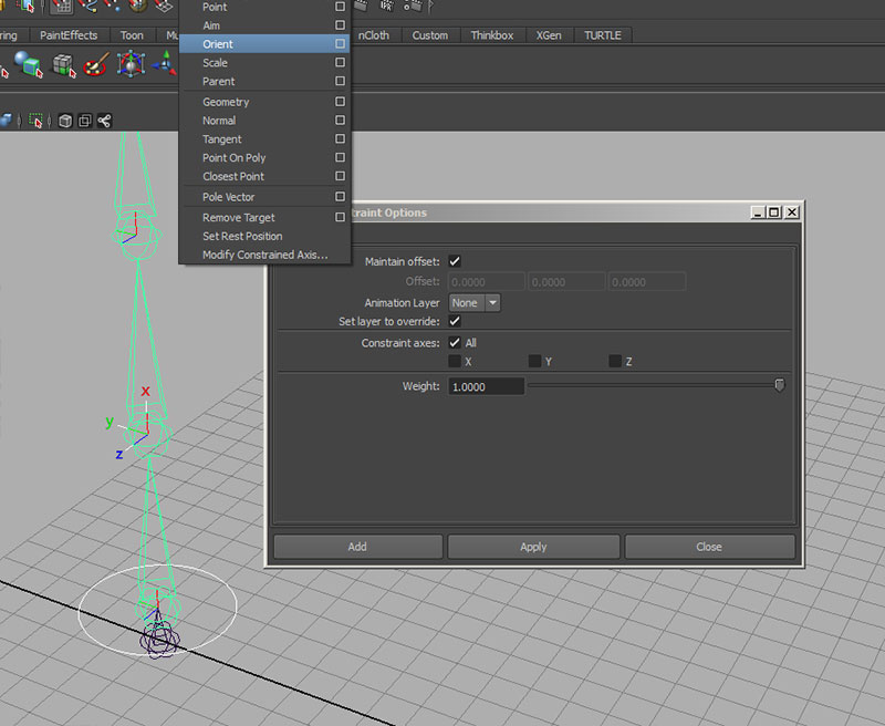
Select the curve as the target and shoulder_jnt as the object to constrain, and use Constrain->Orient with Maintain offset checked.
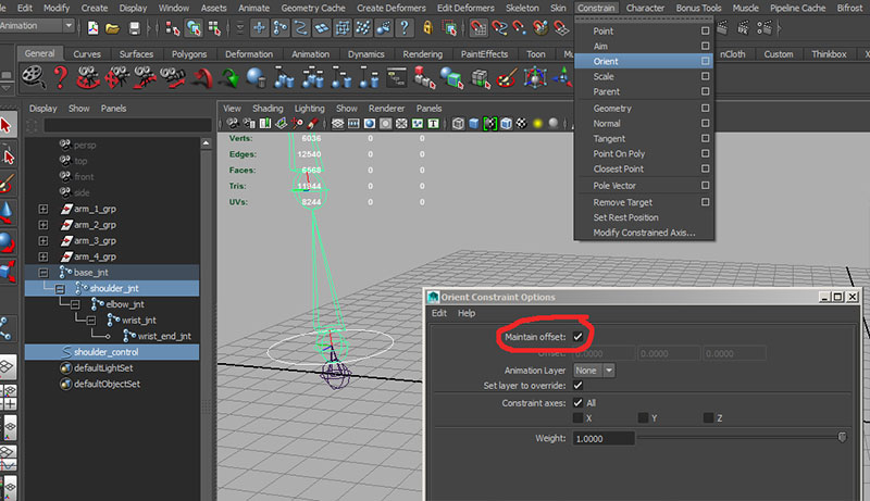
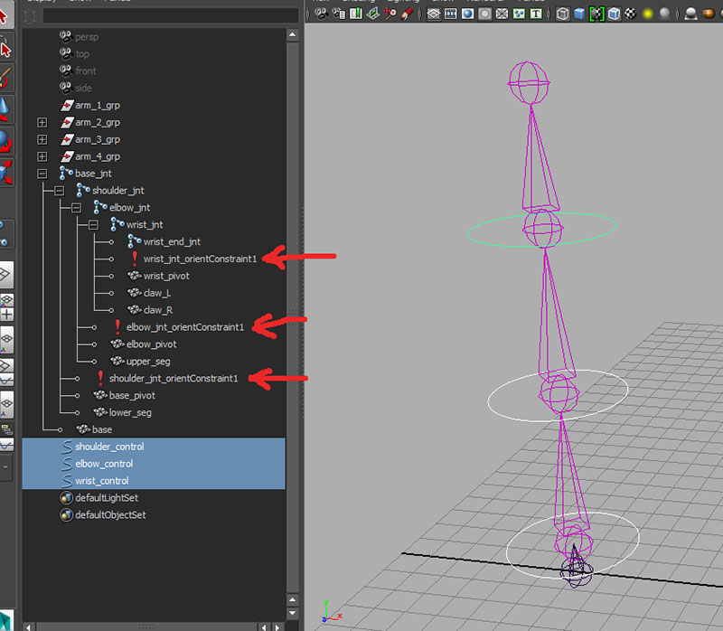
Repeat this process creating a control curve for the elbow and wrist, positioning, freezing transforms and orient constraining the curves. You can find the constraint nodes under the constrained joints (shoulder_jnt, elbow_jnt and wrist_jnt) in the outliner.
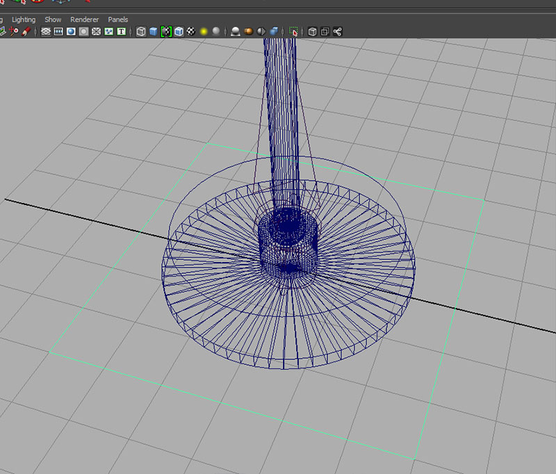
Turn on polygons and test rotating the control curves:
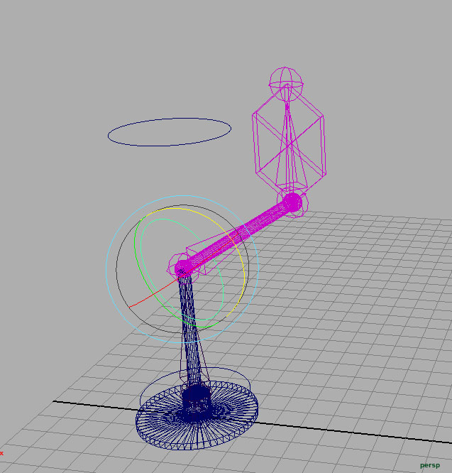
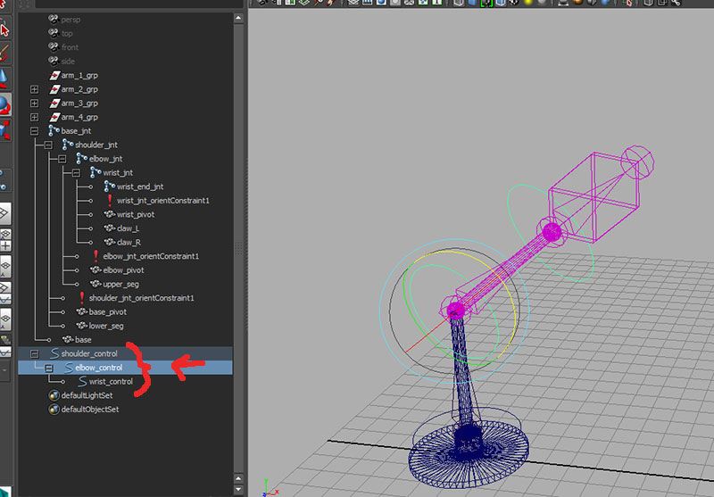
This isn't exactly what we want. What we would like is to have everything downstream react to changes from up the joint hierarchy. Set control curve rotations back to zero and parent controls to mirror the joint hierarchy:
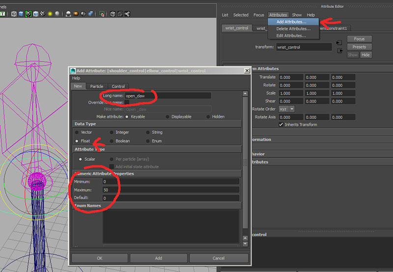
Next we need to control the opening of the claw. Let's create an "open_claw" attribute on the wrist_control. Select the wrist_control open the attribute editor. Under Attributes select Add Attribute..
We want this to correspond to the rotate values of the claw halves, so we need this attribute to be a floating point number (able to take decimal values, not just integers) we want this to be closed at value 0 and not to go below that value, so we want to set the minimum value to 0. Likewise, we want to set a limit on how far this can open and 50 degrees seems like a reasonable value. We'll use this as our maximum value. Default will be closed, so we'll set that will be our default value.
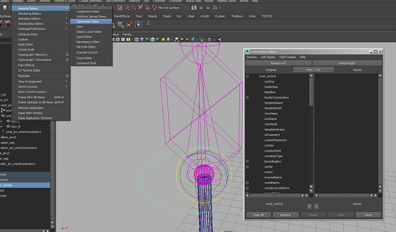
Once we have the attribute we can connect the wrist_control attribute to the rotation of claw_L and claw_R. Select the wrist_control curve and open the Window->General Editors->Connection Editor. This allows us to establish a direct relationship between to attributes, one driving the other.
The object selected becomes the driver (left side of the window) or we could explicitly load a driver by selected the object and using the Reload Left button. Select claw_L and hit the Reload Right button to set this as the driven object.
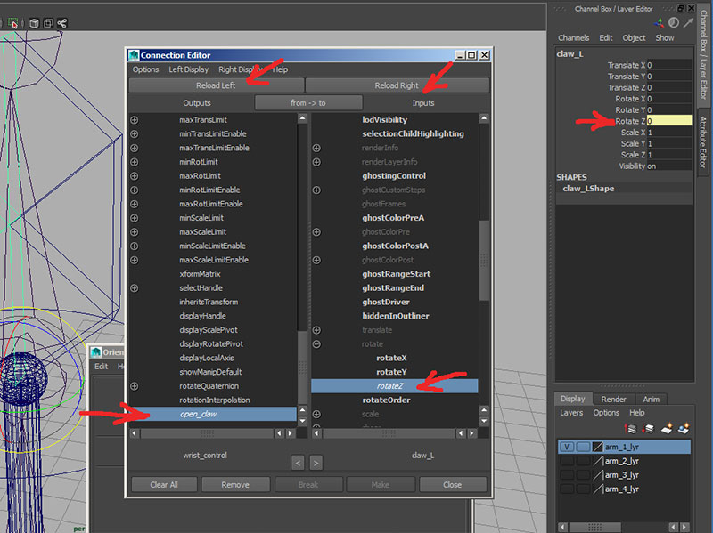
Scroll down the left side (wrist_control) attributes to find open_claw and select. Scroll the right side (claw_L) to find rotate (this will be grayed out since it is a vector attribute) and open to select rotateZ. Once both sides are selected any value changes to the left side will be passed to the right side attribute. Test by changing wrist_control->open_claw.
If we rotate Z on claw_R we'll find that it's rotation is in the negative direction and we can not use the connection editor. Let's remove the connection we just created between between wrist_control open_claw and claw_L, by selecting claw_L rotate Z and right clicking to select "break connection".
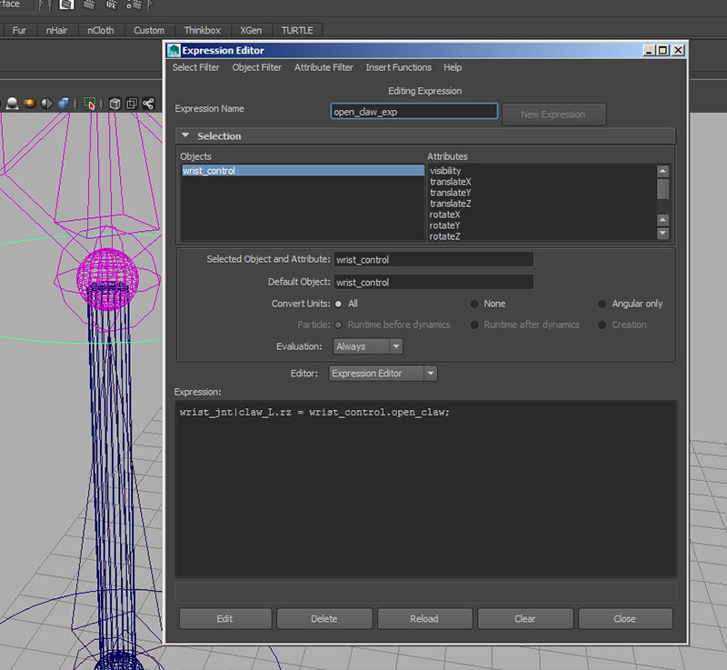
Instead let's open Window->Animation Editor->Expression Editor. Here we have a much more flexible method of connecting attributes with mathematical expressions. With the expression editor open select claw_L. We see that Maya needs a partial hierarchy to uniquely identify the name (I used claw_L in different arm groups in this example scene). Maya uses the "|" vertical bar character to indicate a parent|child relationship. So claw_L must be written wrist_jnt|claw_L. It's attribute is specified with a ".". So the rotateZ attribute of claw_L must be written:
wrist_jnt|claw_L.rz
To connect this to open_claw attribute of the wrist_control, we need to write the expression:
wrist_jnt|claw_L.rz = wrist_control.open_claw;
Enter an expression name at the top of the window (open_claw_exp) and hit create. This should now operate as the connection editor did.
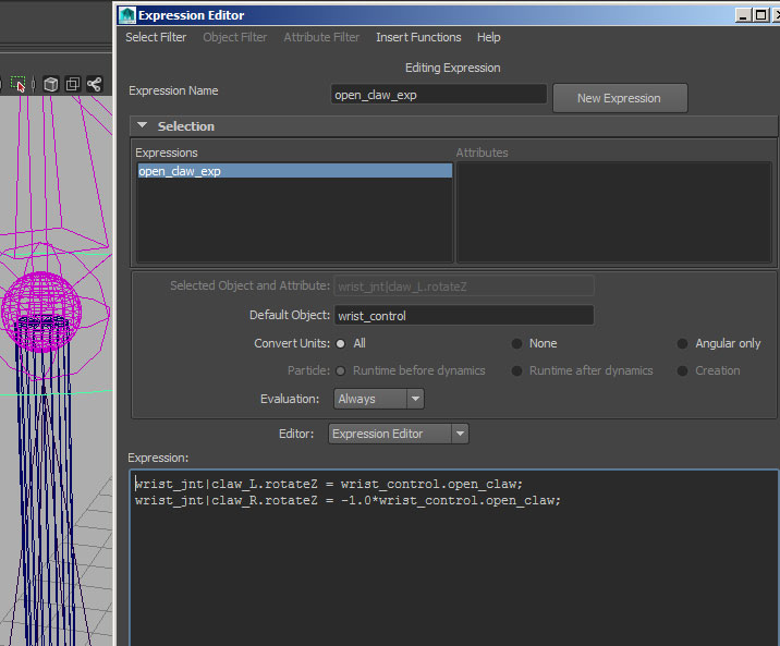
To correct for claw_R, we simply need to multiply wrist_control.open_claw by -1.0
wrist_jnt|claw_R.rz = -1.0*wrist_control.open_claw;
and hit edit.
Let's create one more curve and square curve using the Create->CV Curve tool degree 1 in the top view:
Center the pivot, freeze it's transforms and then parent base_jnt and shoulder_control to the super_mover_control.
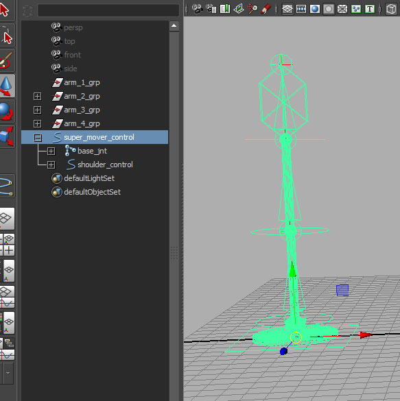
Test move, rotate and scaling controls on the super_mover_control
Since all of our animating will be on the control curves, go back to lock and hide all attributes on the geometry and joints.
Then hide the translation and scaling on shoulder_control, elbow_control, and wrist_control.
Open arm in arm_2_lyr.
Use Skeleton->IK Handle Tool to create an IK chain between the shoulder_jnt and wrist_jnt. Set Current Solver to Rotate-Plane Solver.
Create a nurbs circle and snap to the wrist_jnt.
Freeze it's transforms.
Rename it wrist_control.
Rename the IK handle wrist_IK_handle
Select wrist_control and then wrist_IK_Handle and use Constrain->Point with default options.
Select the wrist_control and then wrist_jnt and use Constrain->Orient with the Maintain Offset selected.
The elbow can be controlled by the Twist attribute of wrist_IK_handle, and adding and simple attribute to the wrist_control, then connecting the two with the connection editor.
Another method would be to create a control curve that would affect the elbow position.
Go to the front view and use Create->CV Curve Tool to draw a triangle curve.
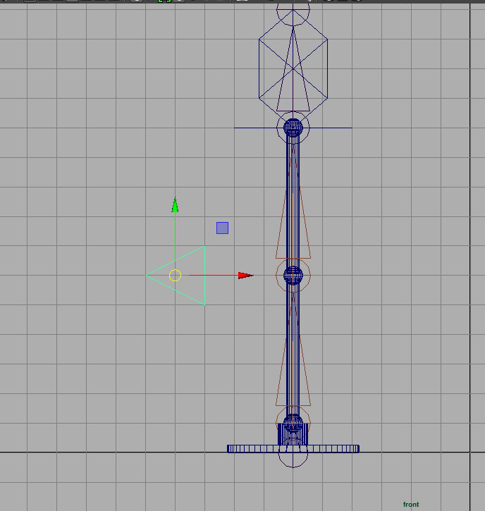
Rename to elbow_control. Create the pivot, freeze transforms and delete by type history.
Select elbow_control and then wrist_IK_Handle and use Constrain->Pole Vector.
Create a super_mover_02_control. Center it's pivot. Freeze transforms, delete by type history.
Parent base_02_jnt, wrist_IK_handle, wrist_control, and elbow_control under super_mover_02_control.
Lock and hide unused channels.
Open arm in arm_3_lyr
Freeze transforms and delete by type history on arm_3_lyr|segment.
Select segment and then joints spline_1_jnt to wrist_jnt and open Skin->Smooth Bind options.
Choose Bind to: Selected Joints and Apply.
Use Skeleton->IK Spline IK Handle Tool with default options and choose spline_1_jnt and then wrist_jnt.
Use Show to turn off Polygons and Joints.
Select the curve and rename to arm_IK_Spline_curve.
Go to component mode and select Control Vertex.
Select Control vertices one at a time and add clusters with Create Deformers->Cluster (default options).
Rename clusters to arm_cluster_1 to arm_cluster_4.
Create 4 nurbs cirles and snap to the clusters. Freeze transforms
Rename circle controls to arm_control_01 to arm_control_04.
Select arm_control_1 then arm_cluster_1 and use Constrain->Parent with Maintain Offset.
Repeat with clusters 2 through 4.
Parent curves.