We can use the polygon operations used in the toy phone example to create organic shapes, and use additional Maya functionality to take advantage of symmetry in our design.
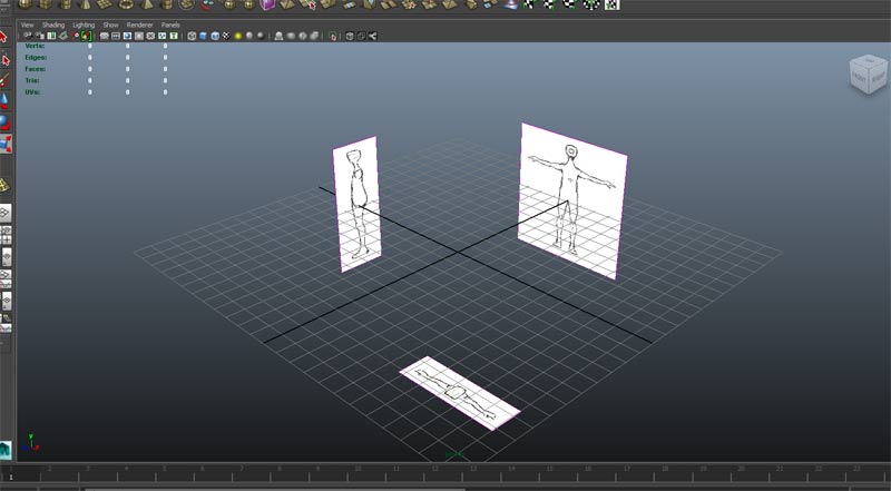
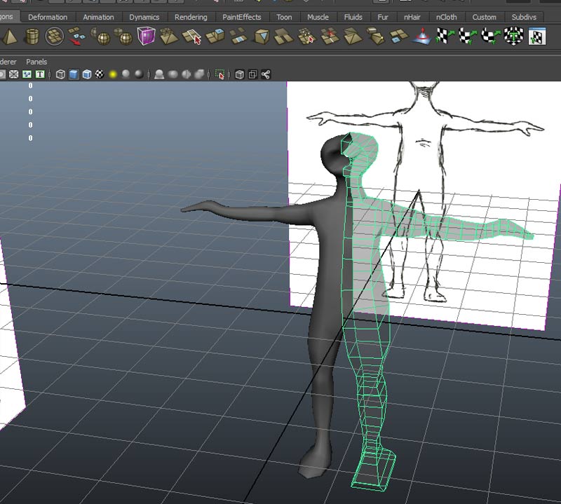
Load the top, front and side view images planes for the abstract figure and position with the image center x,y,z values in channel box
Start by creating a default polygon cube and centering the cube at 0,0,0
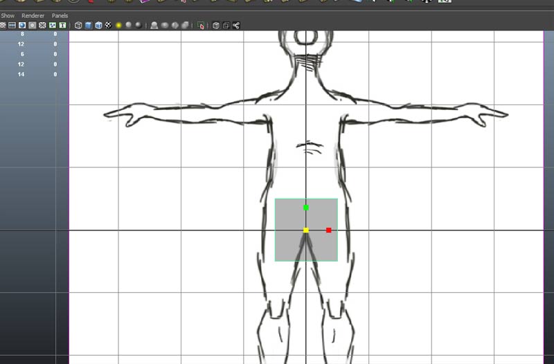
go to component mode and choose vertex. Turn on snap to grid and snap the left vertices to X=0.
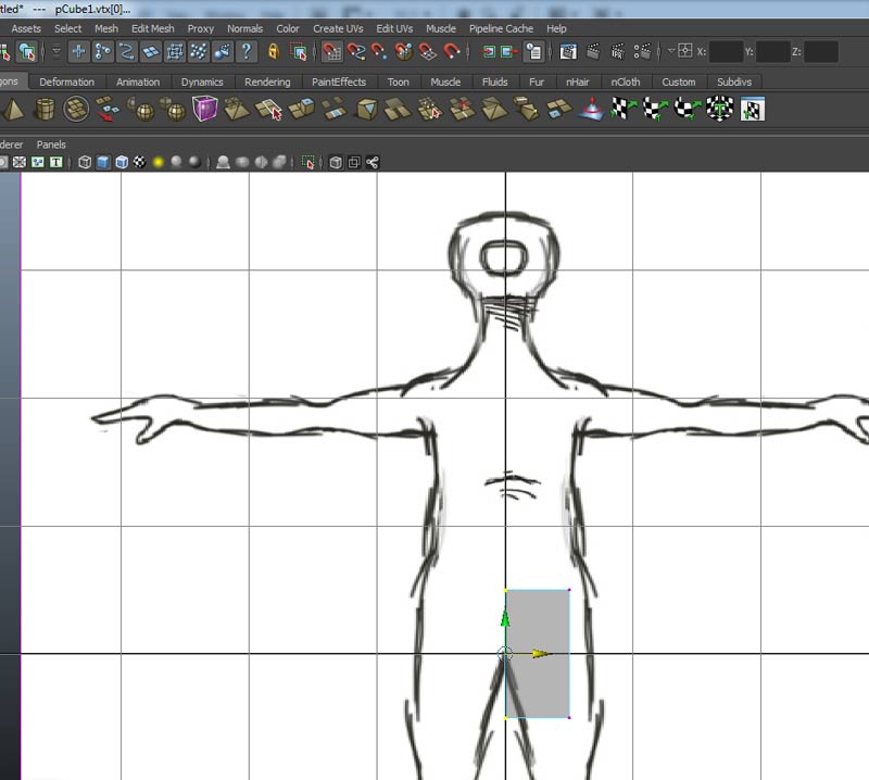
Turn off snap to grid and position the vetices vertically to match the front image plane. Keep the left vertces at X=0.
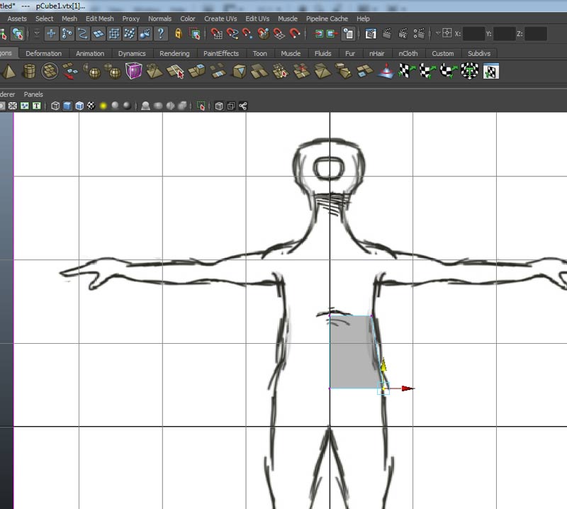
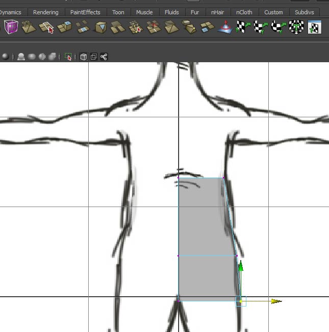
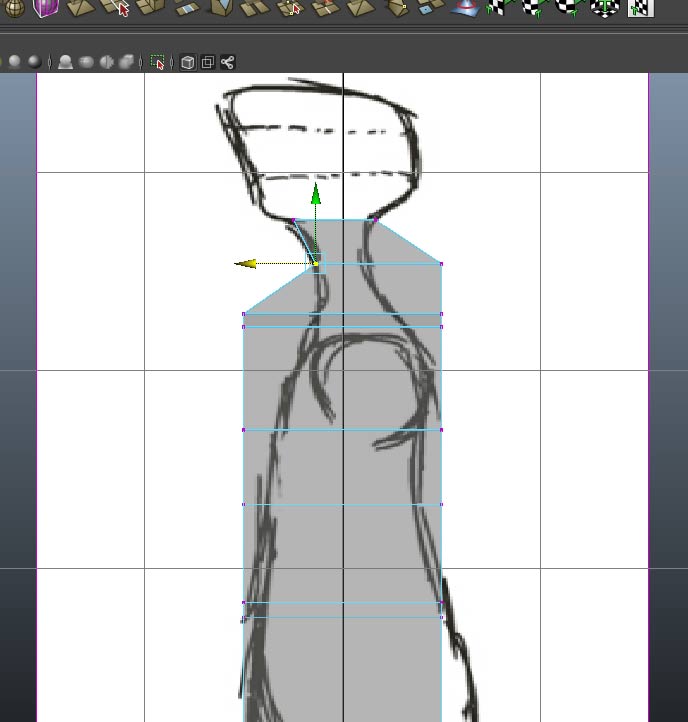
Choose face mode and use Edit Mesh->(Face) Extrude to extrude the bottom face of the cube. Be careful not to use the vertex or edge extrudes...
return to the front view and match the vertices to the image plane.
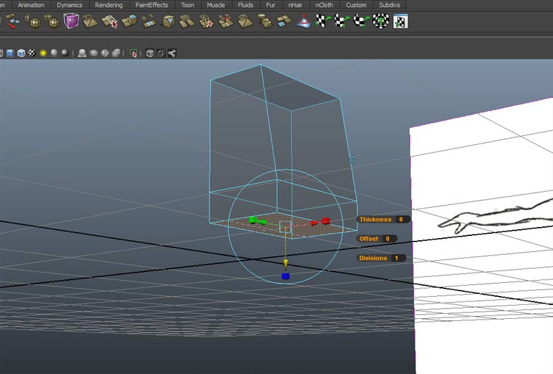
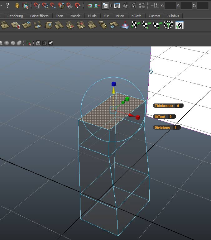
Take the top face and extrude up. Repeat extruding and positioning up along the front view. You can use the "g" key to recall the extrude command. You can also use the move, rotate and scale manipulators from the extruded plane to streamline the process.
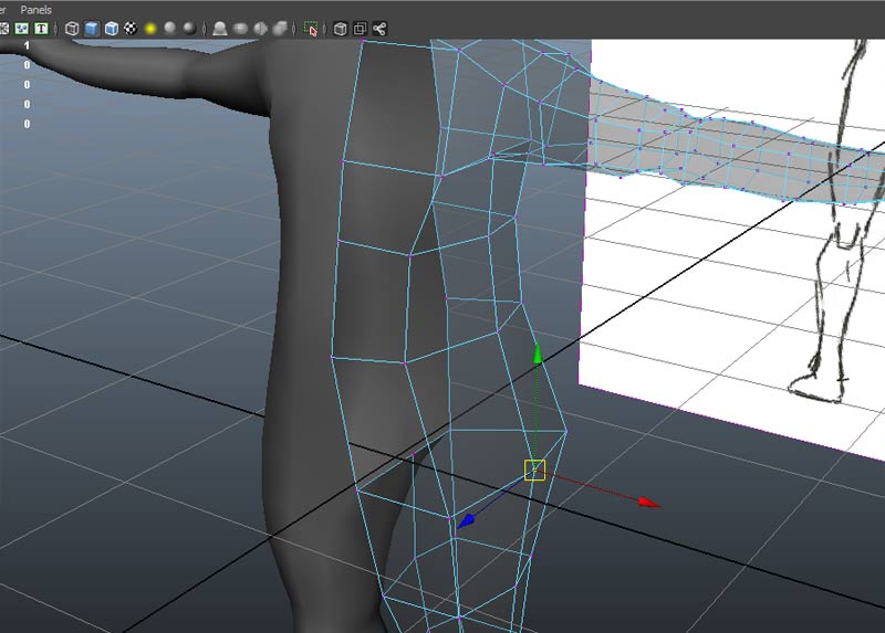
Switch to the side view and reposition the vertices to match the side image plane
Repeat for the entire structure.
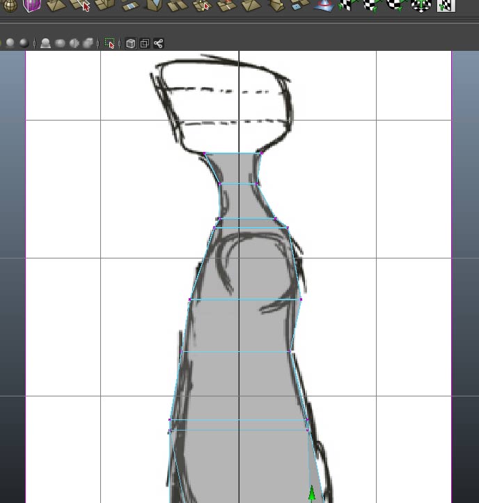
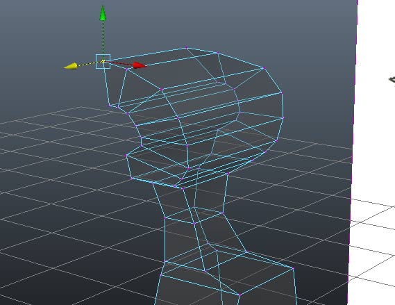
Finish extruding faces to form the "head" of the figure.
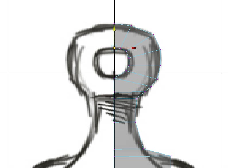
and switch to the side view and reposition the vertices
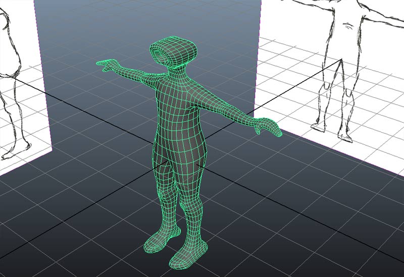
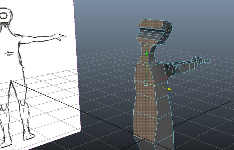
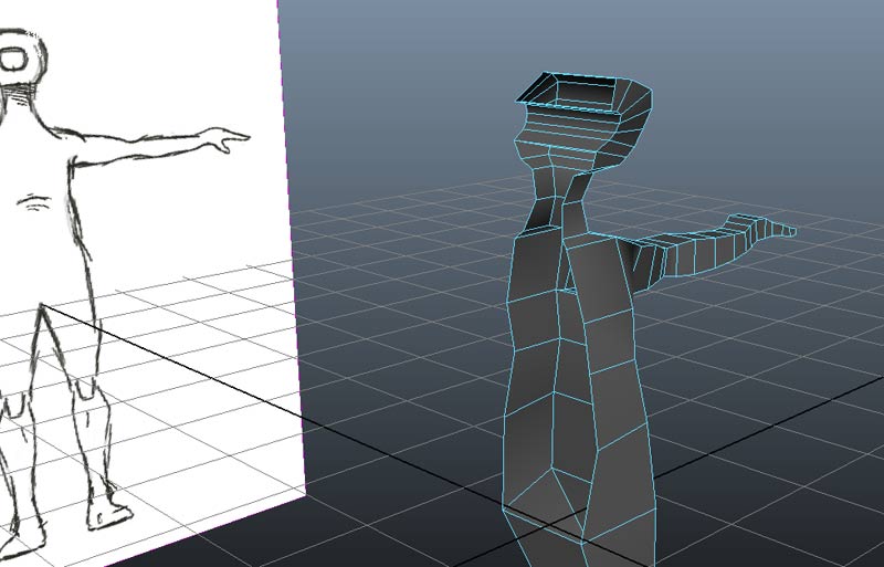
We should begin to recognize the form in the perspective view.
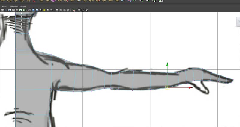
Make sure we have a face that covers the area where we will want to extrude an arm. repeat extruding and alligning faces down along the length of the arm relative to the front view.
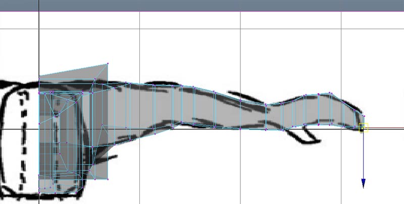
Allign vertices against the top view.
Take the bottom face and extrude down to start the leg
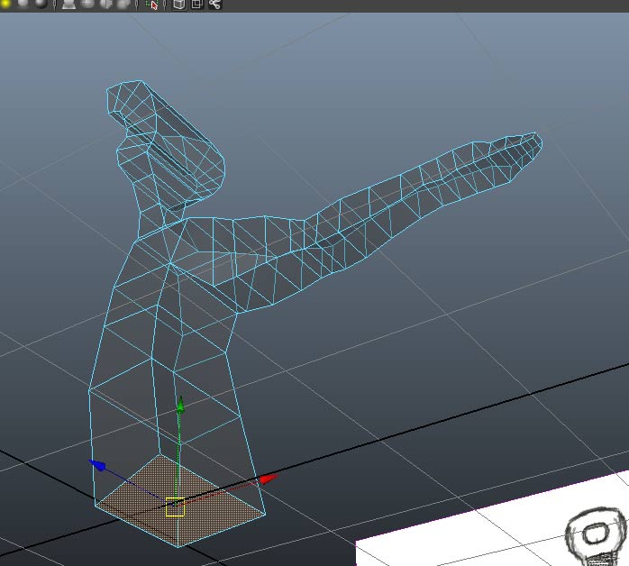
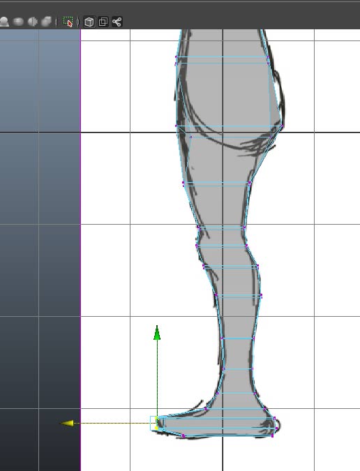
Repeatedly extrude and postion the face to finish the leg in the front view.
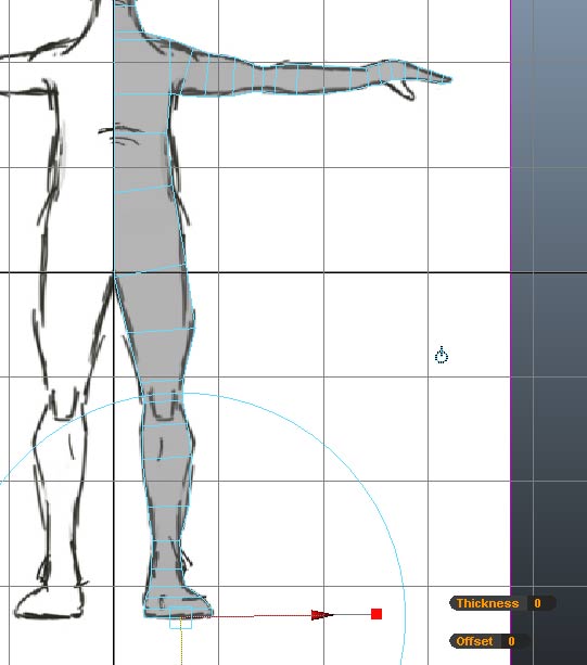
And postion vertices against the side view.
Use the snap to grid individually snap vertices to the X=0 plane. Then select ll faces at X=0.
And use the delete key to delete these faces
At this point check to see if all of your boundary vertices are alligned to the Y axis (e.g. the X coordinate is 0). You can individually select coordinates and use Snap to Grid and the Move tool in the Front view.
A quick way insure that all of your boundary vertices have X=0 is to select them (marquee select boundary vertices in the front view) and open Window->General Editors->Component Editor. Select the vertex.x column and type 0 and return. This will set x=0 for all selected vertices.
We now have enough of the model to use a subdivision proxy to see how our model is progressing
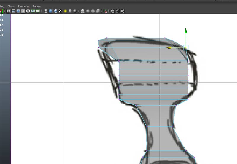
Open the Mesh->Smooth Proxy->SubDev Proxy and scroll down to set Mirror Behavior to Half and Mirror Direction to -X. If the mirroring is not occuring on the boundary, check the location of the pivot, or try Modify->Freeze Transforms or try Edit->Delete by Type->History
The result should look like this
We can add more edge loops with Mesh Tools->Insert Edge Loop Tool
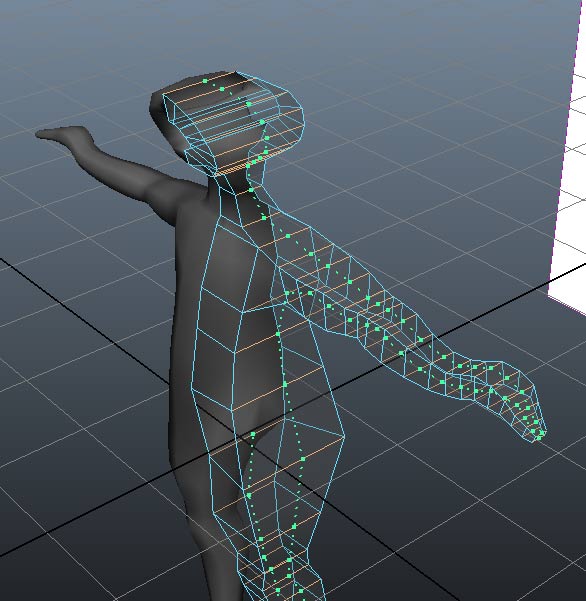
And work with individual vertices to round refine the form
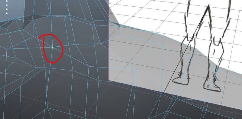
Select the proxy and delete with the delete key. Select the original right side object and use Mesh->Mirror Geometry. Merge with the original by using the Merge with Orginal option and use the -X direction
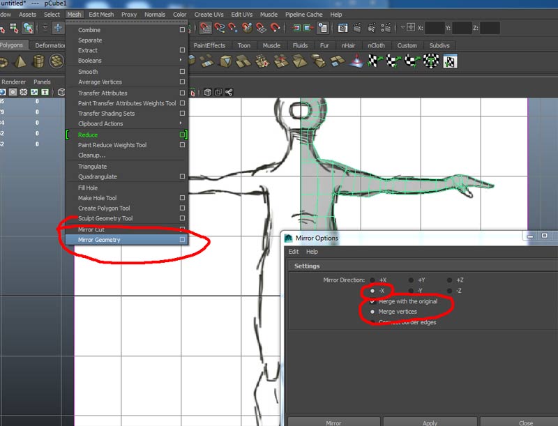
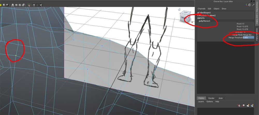
If Maya was over aggressive merging vertices, as in the example below, you will need to access the mirror geometry node and reduce the treshold value.
Use Mesh->Smooth to smooth the resulting object.