Polygons
Nurbs
Subdivisions
Start with a primitive
Interactive Creation (Mesh Tools->Create Polygon Tool)
Importation
Vertex - point in 3 dimensional space
Edge - line segment connecting two adjacent vertices
Face - surface between three or more coplanar vertices
Display->Heads Up Display - To see detailed polygon information on the scene (left column), the select object(s) (middle column) and selected components (right column)
Faces can be classified by the number of edges they have. The minimum number of edges is 3. Faces with 4 edges are called quads, and are generally preferred. Face with 5 or more faces are referred to as Ngons, and can cause trouble in rendering and other areas of the animation pipeline.
The simplest objects you can generate in Maya.
Level of detail can be adjusted by the number of subdivisions, the number of rows of vertices created along a dimension.
Complex models can built using primitives as building blocks.
Topology of the primitive can be changed as long as construction history is available
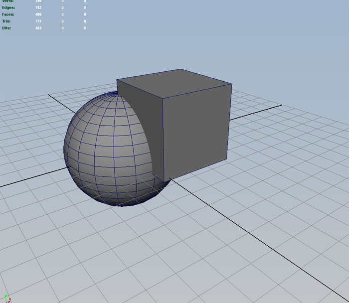
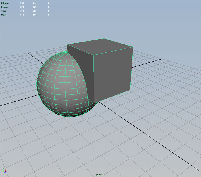
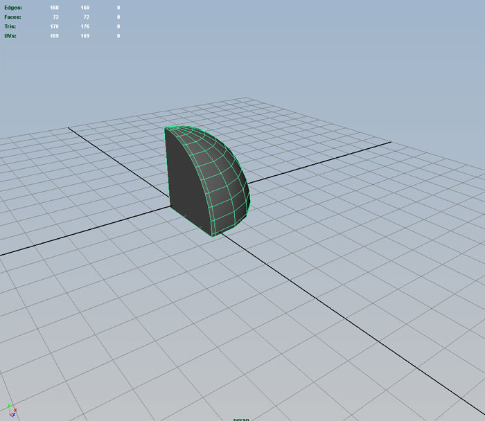
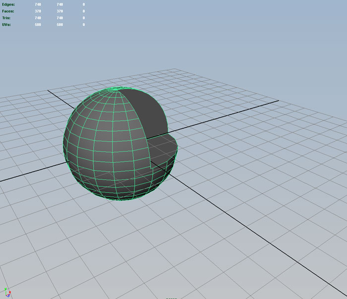
Allows you to combine two models in three different ways, additive (Union), subtractive (Difference) and Intersection. Complex modeling scenarios can be simplified if you are able to view your project as a combination of these three operations and a collection of polygon primitives.
Make sure status line Menu Set is set to Modeling.
Select both objects and Mesh->Boolean->Union
ctrl-Z back and select both objects and Mesh->Boolean->Intersection:
ctrl-Z back and select the primary object, followed by the object to subtract and Mesh->Boolean->Difference:
There are some downsides to using boolean operations. One problem is that they are finicky. Often times models with complex history chains or overlapping objects with coplanar faces will produce a null solution. Sometimes using Edit->Delete By Type->History or repositioning one of the selected objects to provide great overlap will solve the problem.
Also boolean operations usually produce Ngon faces.
These faces can be converted to triangles with the Mesh->Triangulate command
Although better solutions can be generated by first adding a few manual splits of the Ngon faces with the Interactive Split Tool Mesh Tools->Multi-Cut Tool, and rerunning Triangulate:
Further clean up can be done after Triangulate by running Mesh->Quadrangulate.
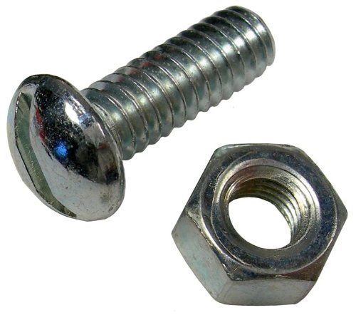
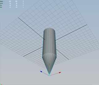
Let's start off with poly cylinder.
Select the option box and set height to 10, radius to 2, and use the Y axis. We'll use 60 divisions around the axis.
Use the channel box to center at 0,0,0.
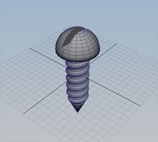
I want to give the bolt a point more like a wood screw. We could do this by taking a cone and intersecting it with the cylinder, but an easier way is to select the bottom center vertex and use the Move Tool to pull it down. If there are several ways to do something, use the simple way:
We can hide the cylinder for now by setting it's visibility to off in the channel box.
Now create a poly sphere with 60 divisions around the axis, centered at 0,0,0 and scaled to 3.5,3.5,3.5
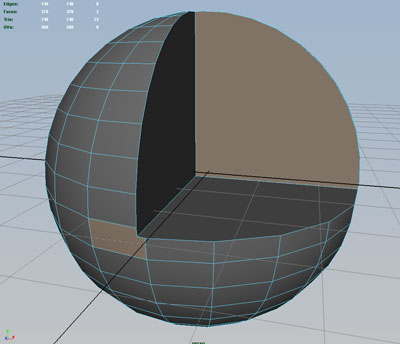
The top of the bolt could be done by using a boolean difference between a sphere and a something flat like a large cube, but we'd have a large Ngon on the bottom. A cleaner solution would be to merge all of the vertices below the equator into one vertex.
Go into component mode for vertices, and set the workspace view to side and rectangular select the southern vertices:
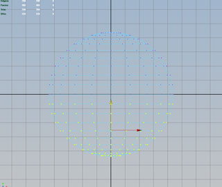
We can merge all these into one centered vertex with the Edit Mesh->Merge To Center command.
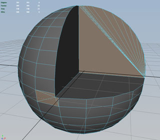
With the new vertex still selected, turn on grid snapping and move the vertex to the origin:
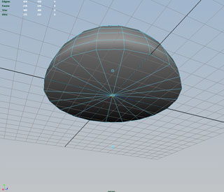
Now the bottom face is nicely subdivided.
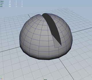
Create a cube and stretch it to create a for the head of the bolt. Use Mesh->Boolean->Difference:
Wouldn't hurt to do a Edit->Delete By Type->History at this point.
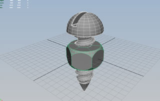
Turn on the visibility of the Cylinder by selecting it in the Outliner and changing off to on in the channel box.
Position the top hemisphere and cylinder and Mesh->Boolean->Union the pair.
Now make a poly Helix. In the option box set:
coils - 7
height -- 3.7
width -- 1.9
radius - 0.25
subd axis - 12
subd coils 50
Axis - Y
12
and scale the result to 3.3.3 and position at 0,-2.2,0
Select the bolt, followed by the helix and do a Mesh->Boolean->Difference.
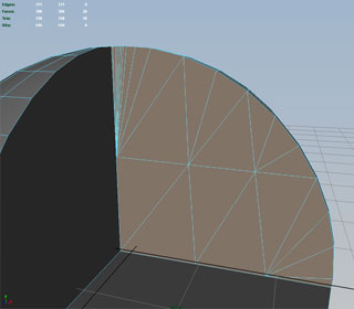
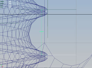
There are a number of problems with the model, but we'll address a few. First, when we look under edge of the bolt head, we see are gradual shading on what should be a sharp edge:
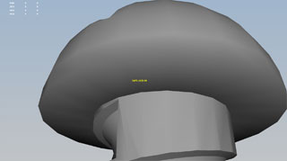
This is a side effect of merging the vertices of the sphere, causing edges which were initially assigned as soft (i.e. smooth). To fix this, click an edge segment and double click an adjacent edge segment. All segments of the edge loop should now be selected.
Now select Mesh Display->Harden Edge:

One dead give away for a computer generated image is razor sharp edges. We can reselect these edges and ad a slight bevel with the Edit Mesh->Bevel command. Use the option box to set the Width of the bevel to 0.7:

We can also bevel the slot edges, but will first need to clean up some Ngons and smaller pieces of geometry. We will do this in class.
Set the visibility for the bolt to off.
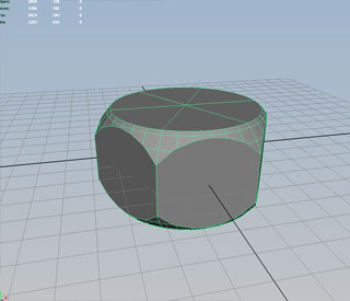
To create the nut, start with a cylinder. Use option box to reset the default options, and change axis divisions to 6. Position at 0,0,0 and scale to 3.8,2,3.8:
Create a Sphere. With the option box set subdivisions around the axis to 36 and subdivsions height to 20. Set the position at 0,0,0 and scale to 4,3.2,4.
Select both the cylinder and sphere and Mesh->Boolean->Intersection:
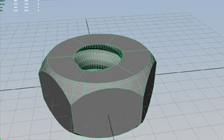
Select the bolt and turn it's visibility on.
Duplicate the bolt with ctrl-D.
Select the nut and then the copy of the bolt and use Mesh->Boolean->Diffference to create threads for the nut:
If you haven't been doing periodic Edit->Delete By Type->History do it now on the nut and bolt objects. Rename the poly objects as "nut" and "bolt". Delete any left over groups which may be cluttering the Outliner.
When you are finished, you can animate the nut and bolt to spin off each other.
Like the wheel example it helps to know the distance the bolt will move with each revolution, which is the distance between the threads (for the values I used for the helix, the threads are about 1.6 apart). To find this distance, use the Distance Tool in Create->Measure Tools->Distance Tool. Change your workspace to side view and
To generate a screen capture of your animation projected at the correct frame rate, use Window->Playblast
Final file is in Y:\Courses\2012-2014\AC5002_Conroy_AU2013\examples\week_4\nut_and_bolt.ma