View->Image Plane->Import Image
Edit Mesh->(Face) Extrude
Mesh Tools->Insert Edge Loop Tool (related command Edit Mesh->Interactive Split Tool)
Mesh Tools->Append to Polygon Tool (related command Mesh->Fill Hole)
Select->Convert Selection
Mesh->Smooth
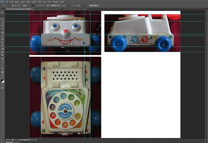
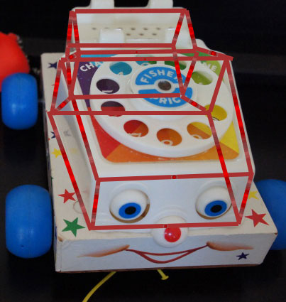
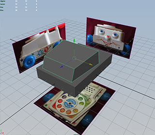
For the phone toy example there are three views to aid in modeling...the top, front and side:
Photoshop can be used to check for distortion from perspective and to do some rough corrections. Use View->New Guide to check how various features line up within the image.
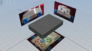
Enter four view mode (space bar to toggle from current view)
Each workspace view panel will have it's own menu. For the top view panel go to View->Image Plane->Import Image.
If you have set up a project, Maya will look in the maya\projects\<project name>\sourceimages directory for the image. Select toy_top.tif.
Repeat for the front and side views.
Go to the persp window.
Select one of the image planes and look at the channel box for the shape node.
The position of the image plane can be adjusted using ImageCenter X,Y,Z, while Width and Height can be used for Scaling the image plane.
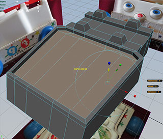
The easiest part of this model is the square base. Create a polygon cube and using the three views scale the cube to fit the base volume:
Select the edges and Edit Mesh->Bevel.
Rename the cube to Base
We're going to use the Layer Editor to allow us to separate different objects. Click Layers->Create Empty Layer to create Layer 1. Double click Layer 1 and rename it to Geo_Lyr.
Select the Base object and RMB hold over Geo_Lyr and select Add Selected Objects. Base is now on the Geo_Lyr.
If we click the V next to Geo_Lyr we can toggle the visibility of the layer. If we click the empty box between the visibility box, we can switch between Reference, Template and Normal mode. Reference mode allows us to see the objects on the layer but prevents us from selecting them. Leave Geo_Lyr set to Reference.
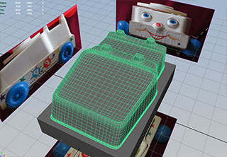
We'll now start to build the plastic upper portion of the body.
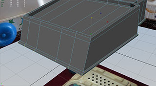
The front section can be formed by stretching a cube:

The back section can also be formed from a cube:
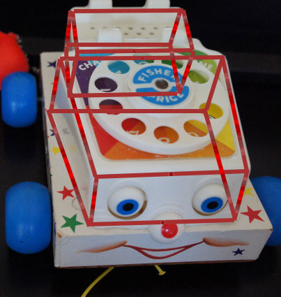
An the back section can be created by extruding from the back face of the front cube, giving us most of the basic form of the plastic section.
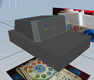
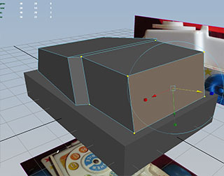
Create a polygon cube and by a combination of scaling, and moving groups of vertices and edges, fit it to the forward area of the plastic body.
Note: Using the Move Tool Reflection setting will help in the front view.
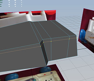
Switch to face mode and select the back face and use Edit Mesh->Extrude. move the extruded face back and scale in slightly to set up the back portion of the body.
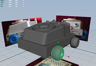
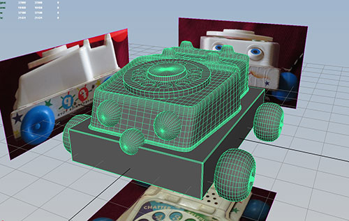
Use the top, side and front view and wireframe and shaded mode to check against the reference images:
and extrude again and portion to the back
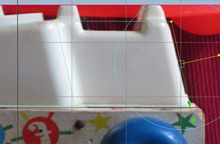
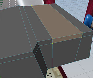
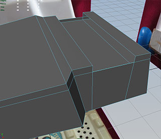
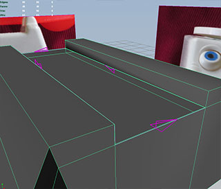
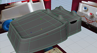
We need some additional edges to create the receiver cradle. Use Mesh Tools->Insert Edge Loop Tool. To line things up with the side view in wiremesh mode.

Use the Insert Edge Loop Tool again to create an edge for the bottom of the cradle:
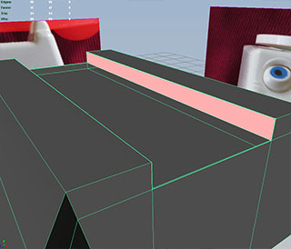
Select the three faces in the cradle area and delete them by hitting the Delete key:
We area going to create three new faces with the Mesh Tools->Append to Polygon Tool.
When selecting edges to create the new face, be sure to follow the direction indicated by the purple arrows. Otherwise the face will be created with reverse normals.
To check for reverse normals, turn off two sided lighting in the panel, with panel menu Lighting->Two Sided Lighting option, and look for blackened faces.
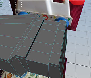
Add more edge loops to define the nibs on the cradle:
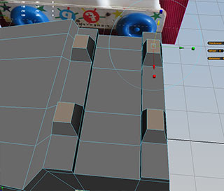
Select the four faces over the nibs and extrude:
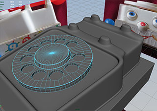
To add an indentation for the dial, we will extrude twice. First to scale in and second to push the faces down.
First, select the faces in the dial surface and extrude. Since faces scale in a non-uniform way, use Select->Convert Selection->To Vertices (while the extruded faces are still selected), and scale in the selected vertices. Then reselect the faces and extude again, pushing the extrudes faces down:
Add another edge loop to create the lip on the bottom of the plastic section, and extrude. You may need to convert to vertices before scaling:
Let's test smoothing by hitting hotkey 3 and determine good places to add edge loops to give the model more definition.
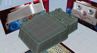
Use hotkey 1 to return to normal viewing mode. To smooth the actual geometry, use the Mesh->Smooth command.
Rename this to Body and add to the Geo_Lyr
The Dial can be created by simply using a cylinder with 3 divisions on the cap:
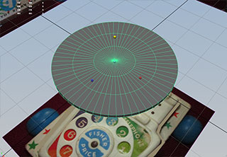
Double click the edge loops and scale to match center cap (on the upper side) and the lower lip (on the under side)
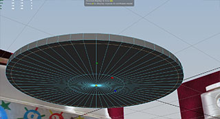
Use the Edit->Paint Selection Tool to select the faces for the cap extrusion:
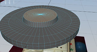
Do ten boolean differences with cylinders and add some bevels:
Typically we would want to create these wheels by defining a curve and rotating it. We will talk about this when we work with nurbs.
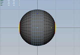
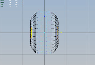
In the meantime, it is fairly easy to make this style of wheel using the Scale Tool with the soft selection turned on, and playing with the falloff radius. Select a vertice at each pole and scale in:
Hub caps can be placed in with a Boolean union. Duplicate and position:
Add eyes and nose:
Files are in Y:\Courses\2013-2014\AC5002_Conroy_AU2013\examples\week_4\phone_toy