Materials or shaders are nodes which control how the surface of an object interacts with light. This would include color, transparency, reflectivity, etc.
All polygons created in Maya are automatically assigned a default material called labert1. Lambert materials do not have specular highlights, while Phong and Blinn materials use different algorithms to calculate highlights. We will talk more about surface properties when we talk about lighting.
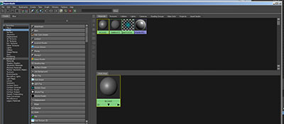
The Hypershade is used to create, modify and assign new materials.
Window->Rendering Editors->Hypershade
The UV Texture Editor map a the 3D surface mesh to a 2D region defined by a U and V dimension,
Window->UV Texture Editor
Copy the week6/phone_text_start.ma to your class example area and open.
Select the polygons and notice that each has a lambert1 tab in the Attribute Editor.
Open the Hypershade (Window->Rendering Editors->Hypershade) and select Blinn on the left side create tab. A new Blinn1 node is created.
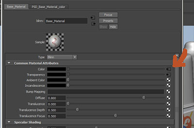
Double click on the Blinn1 node and we can see the the surface properties in the Attribute Editor.
The first attribute is color. Double click the color swatch to the right of color to open a color selector window.
Choose a new color and rename the Blinn1 node to Base_Material
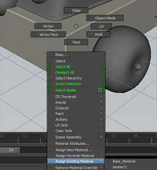
To assign the material to a polygonal object, select the Base object, RMB click and hold over the object and select Assign Existing Material and then the newly created Base_Material.
Create and assign materials to the other objects in the scene.
We use 3D coordinates to describe a vertex on our model
Images from Cubeecraft.com, model by Chris Beaumont:
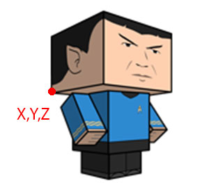
But surface characteristics are mapped to a 2D area. Instead of identifying a point in terms of X,Y,Z, we use U to indicate the horizontal axis and V for the vertical axis.
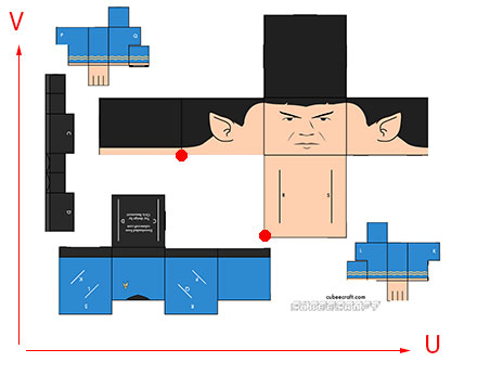
Notice that one vertex can have multiple UV coordinates.
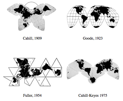
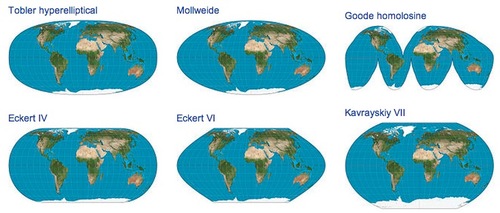
While mapping cubic shapes is fairly straight forward, curved surfaces require a combination of seams and distortion of the faces. Cartographers have been dealing with these issues for centuries:
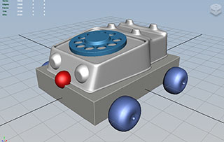
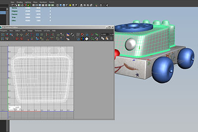
For our phone toy model, we will need to establish a UV mapping for the object.
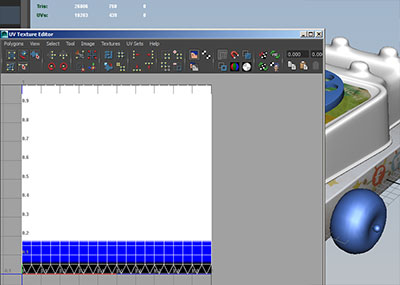
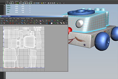
Select the Base object and open the UV Texture Editor (Window->UV Texture Editor)
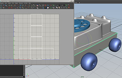
Here we see the default mapping for the cube primitive before we scaled the object to match our image planes.
There are several methods of remapping the object, depending on shape and complexity. Here we will use the standard menu command: Create UVs->Automatic Mapping
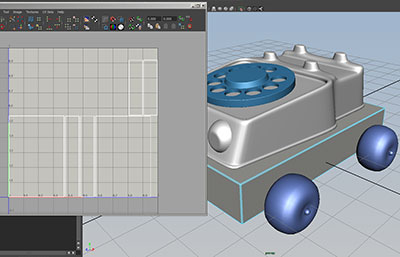
In the automatic mapping, the faces match the aspect ratio of the polygonal faces.
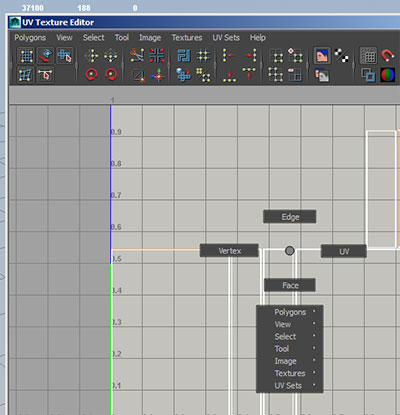
Notice that we can right click in the UV Texture Editor to select different polygon components (vertex, edge, faces, and UV) but we can only move, rotate and scale UVs in the UV Texture Editor.
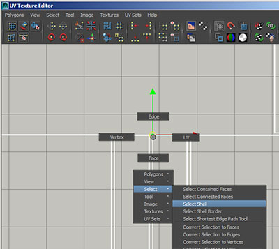
The automatic mapping created groupings of connected UVs called Shells. To select the shell containing a UV, RMB and Select->Select Shell:
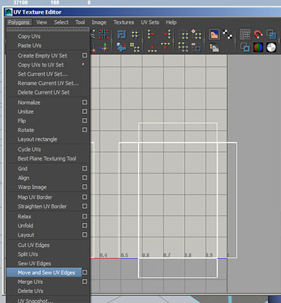
We can join shells together by common edges. Select an edge shared by two shells, and use the UV Texture Editor menu command Polygon->Move and Sew UV Edges.
We can continue to use this command to attach the sides to the top face:
We can also use Polygon->Cut UV Edges to break faces off of a shell.
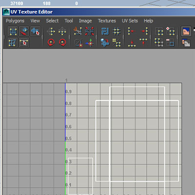
Select the shell associated with the bottom face and scale this down. Depending on how a face is used (for instance a face may not be seen by the camera), a face may have less need for UV map area.
Conversely, we can scale up the shell for the top and sides because the resolution of the map will be best used in these areas:
Set you project and copy Y;\Courses\2012-2014\AC5002_Conroy_AU2013\examples\week_6\phone_psd_start.ma to the scene directory.
We will create a psd network which will allow us to work between Photoshop and Maya.
In the UV Texture Editor menu select Image->Create PSD Network...
Note the file location under Image Name. Make sure Include UV Snapshot is checked.
We could also darken the UV Settings Color Value since our current background color is fairly light.
Under Attribute Selection, select color and click the right arrow to move this to the Selected Attributes. If we were going to use Photoshop to control other attributes, we also move these to the Selected Attribute section.
Hit Create.
Photoshop is under Start->All Programs->Graphics 2D
File->Open to open the PSD file.
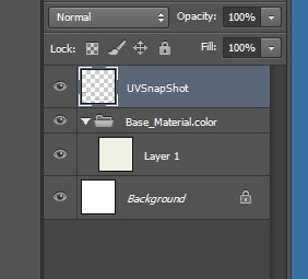
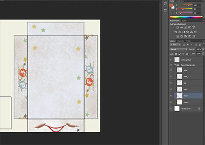
In the Photoshop Layer Window, notice that Maya created three layers.
The top layer UVSnapShot contains the outlines of our UV faces.
The middle layer Base_Material.color is a layer folder where we will place our color texture images.
We will not be using the Background layer.
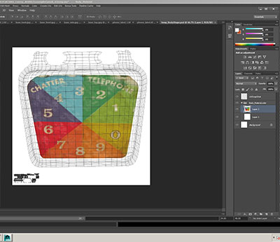
Open the four base_* files in the Y drive work area examples\week_6\source_images in Photshop. Copy and Paste these into the Base_Material.color layer folder. Paste the base_side image twice.
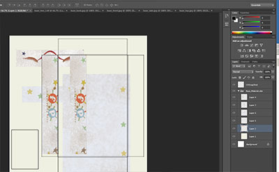
Select layers in Base_Material.color and use Ctrl T position, rotate and scale images to cover the appropriate faces. Use the Move Tool to terminate ctrl T:
File->Save to write the changes into the PSD file.
You may need to force Maya to reload the PSD file.
Double click the Base_Material node in the Hypershade and click the arrow after the color attribute:
and click the Reload button under the Image Name field.
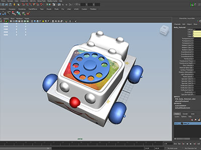
If you use use the 6 hotkey for shading mode, you will see the loaded textures.
We can repeat this process for label under the dial.
We can auto map the UVs. For simplicity we will only concentrate on the shell under the dial:
Create a PSD Network and load scale the dial
Load the PSD in Photoshop and copy and scale the phone_label.tif from the example area.
Save in Photoshop and reload the file in Maya:
We can do some simple textures using Maya's procedural utilities available in the Hypershade.
If we select the Eye_Material and select the checker board button after color:
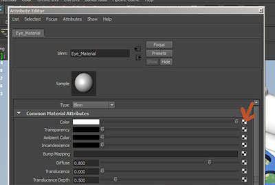
Maya allows use to attach procedural utilities to the color field.
If we select the Ramp Utility, we can change the colors and Interpolation type from Linear to None:
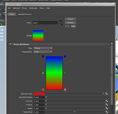
To:
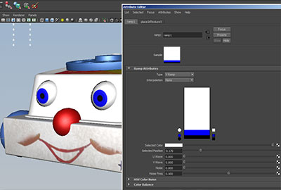
The ramp takes advantage of the default UV layout of sphere primitives to color the lower region of the UV map blue and black: