Non-uniform rational B spline surfaces
If we sculpt with polygons, we manufacture with NURBS
When the surface can be defined in terms of curves, NURBS are often the solution we want to consider.
First switch menu set to Surfaces
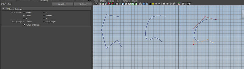
First open the option box for Create->CV Curve Tool
Create 3 similar 6 point curves, one each for Curve degree: 1 Linear, 2, 3 Cubic:
Degree - the largest exponent used in the equation used to compute the curve. Degree one is linear, composed of straight lines.
CVs - Control Vertices - points which influences curvature. CVs are ordered and the order has direction.
Spans - sub sections of the curve. Higher degree curves will have fewer spans (for a given number of CVs) and a greater degree of smoothness between spans.
EPs - Edit Points - (AKA Knots)- connecting points between spans. Unlike CVs, EPs will always be on the curve. The shape of the curve determines the position of the edit points.
Hull - linear connections between CVs.
Parameterization - curves are computed as a function of the position of a point along the curve, which we will refer to a 'U'. Curve and surface functions in Maya work most effectively when the EP locations have numeric values which are whole numbers.
RMB click and hold over the circle to see the component options: curve point, control vertex, edit point, hull and object mode.
Try selecting each and manipulating the components.
Notice the number of CVs and EPs
Look at each curve in the attribute editor. notice the Min Max Value, the number of spans and the degree.
When moving CVs, notice what portion of the curve is affected (2 spans for degree 1, 3 spans for degree 2, 4 spans for degree 3).
We can think of surfaces as curves with an additional dimension. Here parameterization is in a U and V direction. Isoparms on a surface function in a similar manner to the way edit points do on a curve.
All NURBS surfaces are 4 sided patches. To test:
Create->NURBS Primitives->Sphere
and click select CVs at the poles. Move to open the patch.
But, if we can open the pole, why can't we open the seam running from pole to pole? Select the sphere and open the attribute editor. Notice the Form U and Form V attributes. These Form attributes can be of type Open, Closed or Periodic.
In an Open curve or surface, you can overlap the start and end points, but they still can be manipulated independently.
A Closed curve or surface will weld the start and endpoint together.
A Periodic curve or surface is similar to Closed, but has additional unseen spans which ensure smoothness.
If we look at a NURBS cube:
Create->NURBS Primitives->Cube
We find that the object is a group of 6 NURBS patches.
Surfaces can have different degrees on their U and V dimension.
NURBS surfaces are converted to polygons at render time, which is refereed to as tessellation.
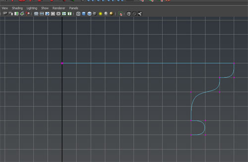
Create a CV degree 3 curve with snap to grid on.
Create->CV Curve Tool
You get sharp corners with multiple CVs placed on top of each other. While CV multiplicity, or overlapping CVs, is generally not recommended, for simplicity sake we will use them in this example.
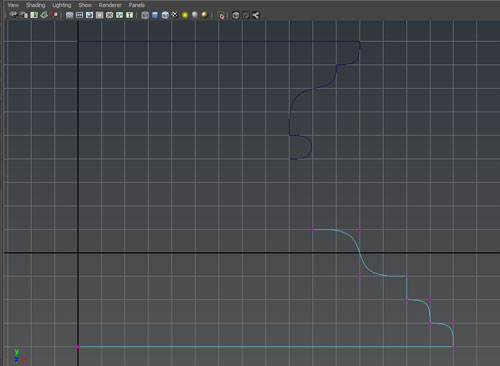
Create a curve similar to this:
Create a second curve similar to this:
Select both curves and check the number of spans and min max value in the attribute editor.
We can attach curves together with
Edit Curve->Attach Curves
We can get a sharper or smoother connection by changing Method in attach curve node from blend to connect
If the wrong end of the curve is connect we can reverse the direction by changing the reverse1 and reverse 2 attributes in the attach curve node
It is usually a good idea to save the old curves. Give them meaningful names, create a group "old_curves" and put them in that area. Set visibility of the group old_curves to off.
Check parameterization of the new curve. Are the min max value and # of spans equal? If not, rebuild the curve with:
Edit Curve->Rebuild Curve
We will set the parameter range from 0 to the number of spans and keep CVs:
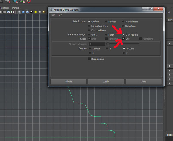
Check the Min Max value of the attached curve before and after the rebuild.
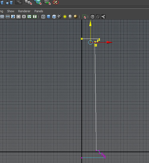
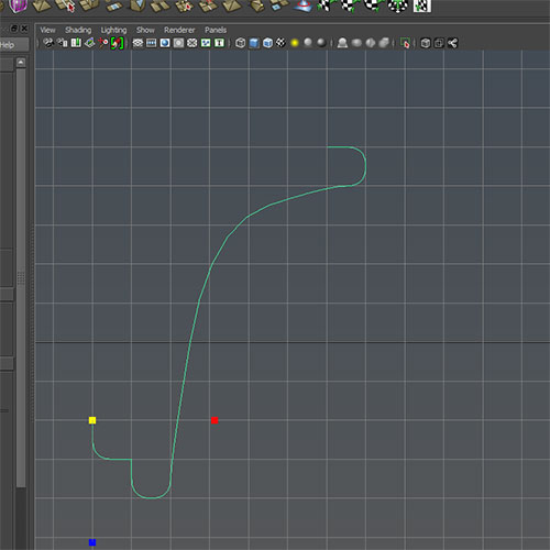
Grab the top C and stretch the curve and position the edge points along the Y axis:
Create a surface by revolving the curve around the Y-axis and using degree cubic:
Surface->Revolve
Look at the revolve node in the attribute editor. Notice that we can revolve around one or more of the 3 axis. We can also revolve with a linear or a cubic degree.
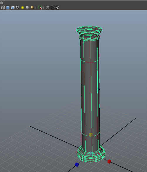
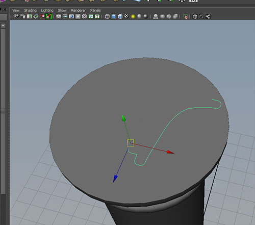
We can scale this to the desired proportions. Rename to lvl1_column and save the profile curve in the old_curve group.
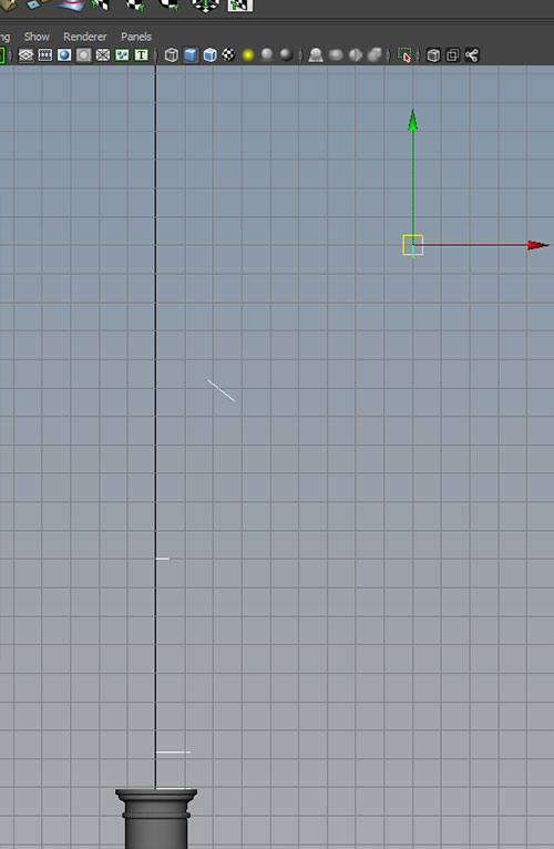
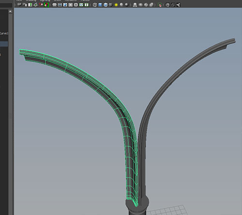
Create a new curve similar to this:
Rename the curve lvl2_arch_curve. Scale it down and position on top of the column.
Use duplicate (ctrl-D) to create copies of the curve and position them like this:
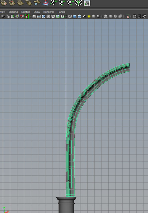
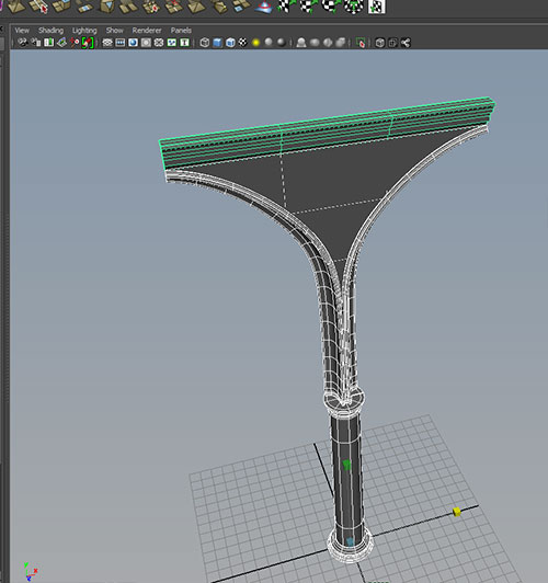
If we select the curves in order from lowest to highest, we can use create a surface that spans these curves:
Surface->Loft
Open the loft node in the attribute editor and experiment with the Degree, Uniform, and Close.
Adjust the Section Spans. What are the pros and cons of increasing and decreasing this value?
Duplicate the half arch and scale -1 in X.
Go to the back of the half arches and RMB click and hold to select isoparms. Select one of the inner edge isoparms and create a curve with:
Edit Curves->Duplicate Surface Curves
Repeat for the other half arch.
If we turn off visibility for the arches we have these two curves:
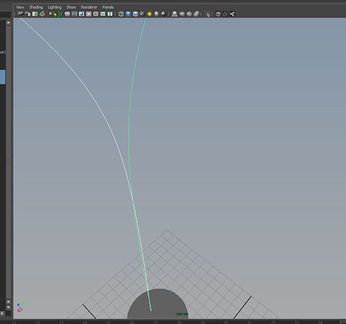
Because of a slight curvature at the bottom, these curves intersect. To cut at the intersection, select both curves and use
Edit Curves->Cut Curve
and delete the old portions of the curve below the intersection. With both remaining curves selected we will attach with:
Edit Curves->Attach Curves
with option connect for attach method.
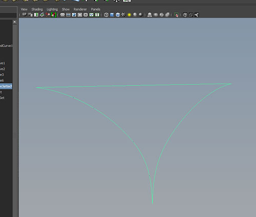
To close, use:
Edit Curves->Open/Close Curves
with Shape: Preserve checked. The result should look like:
To create a surface from this curve use:
Surface->Planar
Notice when selecting the resulting surface and viewing CVs we get:
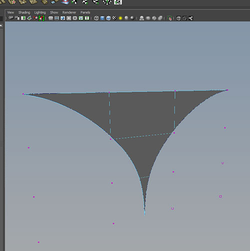
We still have a 4 sides patch, with some parts not visible.
Turning everything on and adding an extra lofted rim:
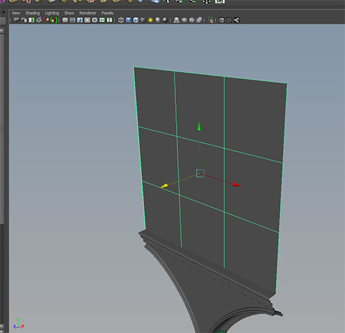
Create a NURBS plane in the Z direction with
Create->NURBS Primitive->Plane
and translate and scale to the top of the column group.
Create 2 NURBS circles, one with a sweep of 180 degrees, and one with 360. Scale and position as shown:
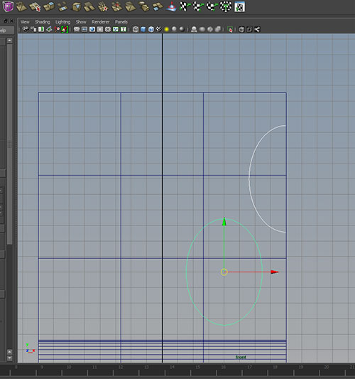
We will use these window frame curves for two purposes. The first is to control the sweep of a profile curve.
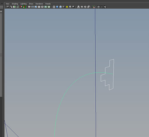
Create a linear CV curve and close the curve with with Shape:preserve selected:
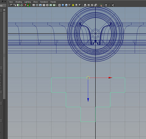
Scale this down and position against the circle curves:
Select the profile curve first and the semi-circle path second, then use:
Surface->Extrude
with Orientation: Path Direction selected.
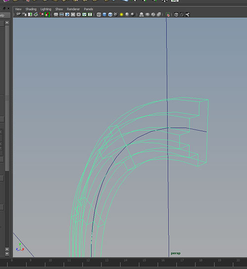
Extrude is similar to loft, but while loft creates a surface from a series of profile curves, extrude creates a surface from a profile curve following a path.
Repeat the process for the other circle.
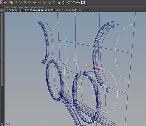
Delete history on the new surfaces and move the profile curve to the old_curve group.
Group the circle curves and the window frames, duplicate, and scale the duplicated group -1 in the x direction.
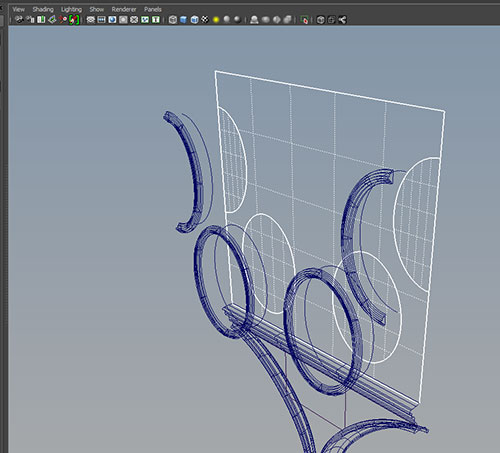
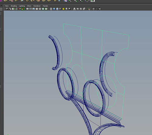
The second function of the window frame curves is to cut holes in the plane. First we must project the curves onto the plane.
Select the 4 window frame curves followed by the plane. Use
Edit NURBS->Project Curve on Surface
and use option Project Along: Surface Normal.
To cut out the openings, select the plane and use:
Edit NURBS->Trim Tool
and select the portion of the surface to keep, then hit enter:
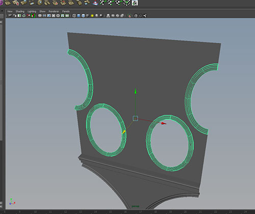
save the curves, reposition the window frames and we should have:
 4
4
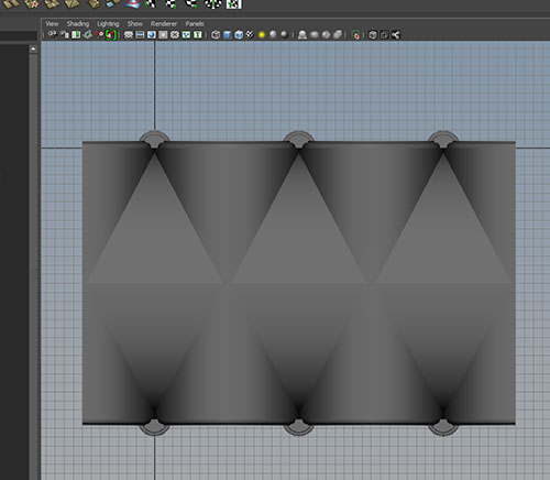
Create a curve for the ceiling vault. Duplicate and loft:
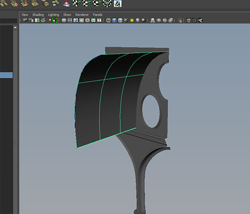
Duplicate the surface and scale x -1:
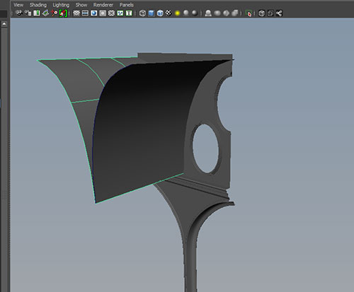
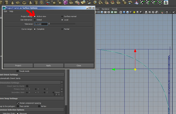
Take one of our ceiling curves, rotate and scale. Project this curve onto the two vault surfaces using
Edit Surfaces->Project Curve on Surface
with the Project along Active View option selected:
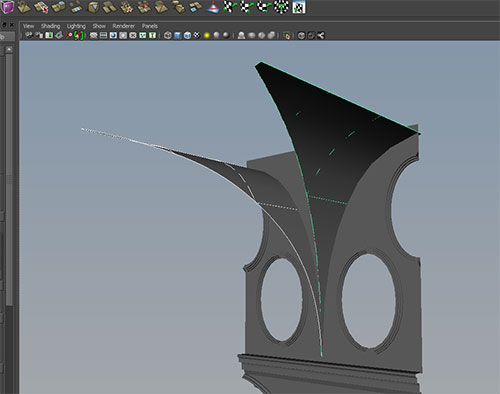
Repeat with the second ceiling surface.
Use the Trim tool to remove the extra area:
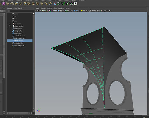
Now we can RMB click and hold to select the Trim Edge of each vault surface. To convert this to a curve use:
Edit Curve->Duplicate Surface Curve
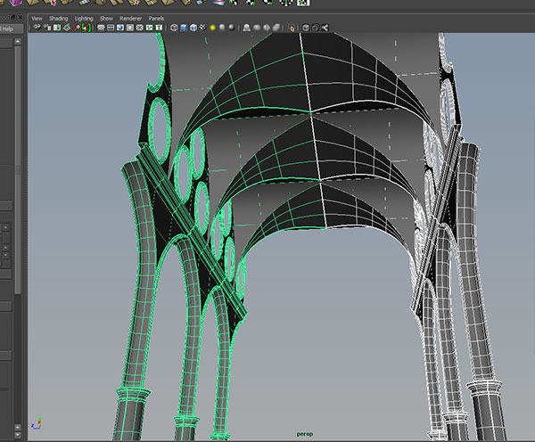
to create the boundaries of our third ceiling surface:
Select both trim edge curves and loft:
Grouping the sections allows us to duplicate and create a larger structure: