Let's revisit the example of parented cubes in:
Open Y:\Courses\2012-2014\AC5002_Conroy_AU2013\examples\week_3\arm.ma
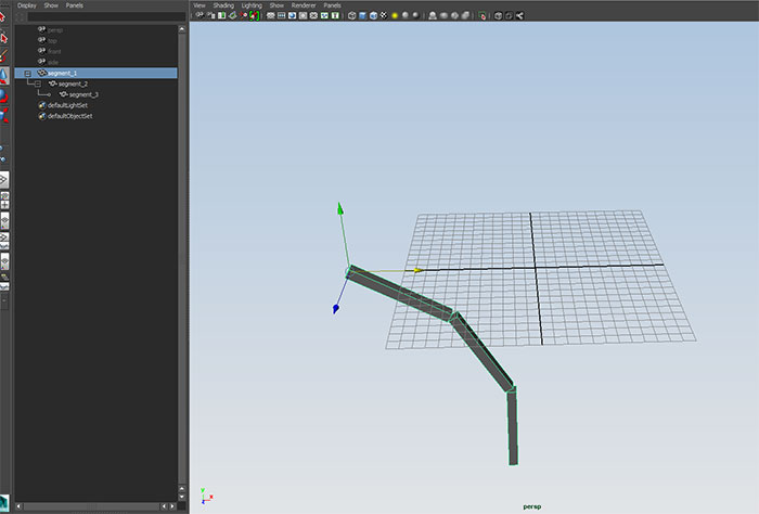
In this example we saw transformations cumulatively working their way down a hierarchical chain.
Go to time t=1, switch to the Animation Menu Set and use:
Skeleton->Joint Tool
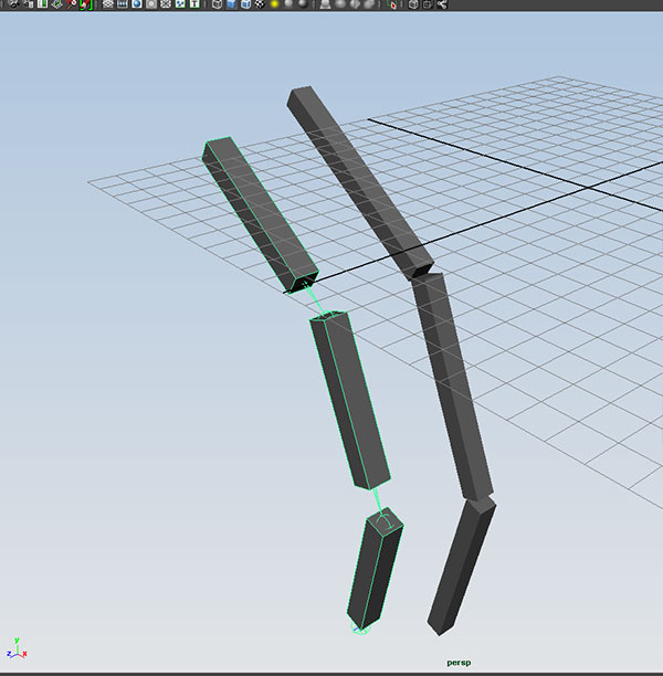
Click this four times in a straight line on the grid:
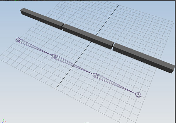
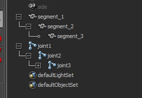
when we look in the outliner, we see the joints created have the same hierarchical structure as our arm cubes:
We can create three name cubes, and position them at each joint:
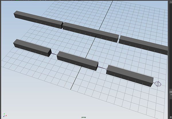
Now parent pCube1 to joint1, pCube2 to joint2 and pCube3 to joint three.
We can key the three joints to
t=1 rz=0
t=50 rz=45
t=100 rz=-45
t=150 rz =0
And the joint chain will give us the same behavor as the parented cubes.
Go to t=1, and delete the cubes and create a cylinder with 30 divisions along its height. Position it over the joints:
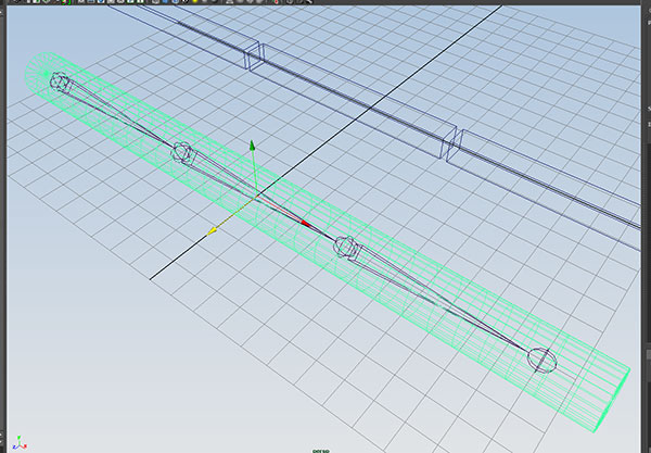
Now select the cylinder and then joint1 and use:
Skin->Bind Skin->Smooth Bind
check the animation:
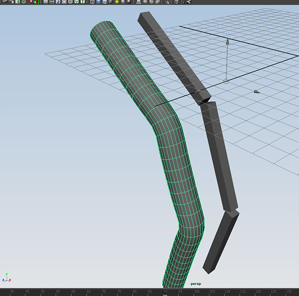
With the joint chain, we can deform a single mesh with the movement of the skeleton.
Skeletons in Maya are hierarchical control structures for deforming bound geometry. They function in much the same way that bones and joints do in our bodies.
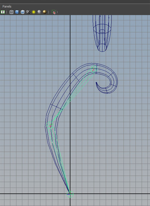
Open Y:\Courses\2012-2014\AC5002_Conroy_AU2013\examples\week_9\joints_start.ma
and go the the side orthographic view.
Switch to the Animation Menu Set and use:
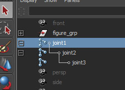
Skeleton->Joint Tool
and click three times to create a joint for the hip, knee and ankle of the "leg" of the figure
Look in the outliner to see what was created.
Rename joint1 to Hip_R, joint_2 to Knee_R, and joint_3 to Ankle_R.
Test rotating the three joint, and crtl-Z back to original position.
Here, we give Maya the rotation values of the joints and Maya calculates the location of the endpoint of the joint chain. We call this forward kinematics.
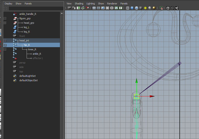
Now open the option box for
Skeleton->IK Handle Tool
and set Current solver to Rotate-Plane Solver, and click on the Hip_R and Ankle_R.
Maya creates a new component called ikHandle1. Rename this to Foot_IK_Handle_R
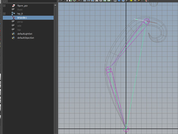
Select the Foot_Handle_R and move with the move tool.
Here, we give Maya the location of the endpoint of the chain and Maya calculates the rotation values of the joints which are needed to generate that endpoint location. This is reverse of forward kinematics, so we call this inverse kinematics.
But...what if there are multiple solutions to the IK problem? Select Foot_IK_Handle_R and open the channel box. Select Twist and MMB alter the value. What happens to the joint chain?
crtl-Z back to the original position.
Select Hip_R and change the translate X to -8
.
Move to front view and use Skeleton->Joint Tool with one click add a new joint near the head on the y axis:
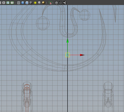
Rename joint_1 to Head_jnt
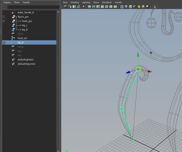
Select Hip_R and then Head_jnt, and use the p hotkey to parent the hip to the head.
To create the left leg joints, select the Hip_R, and open the option box for
Skeleton ->Mirror Joint
We are mirroring across the YZ plane, click YZ for Mirror across. We want to have Maya automatically change the _R names to _L, so enter _R for Search for and _L for Replace with: Click Mirror:
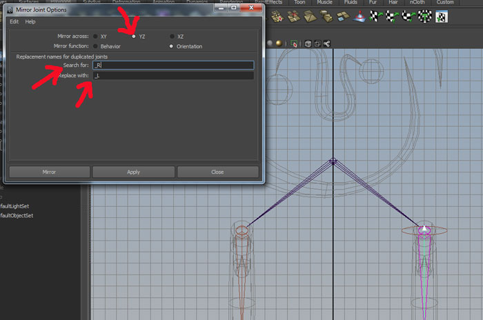
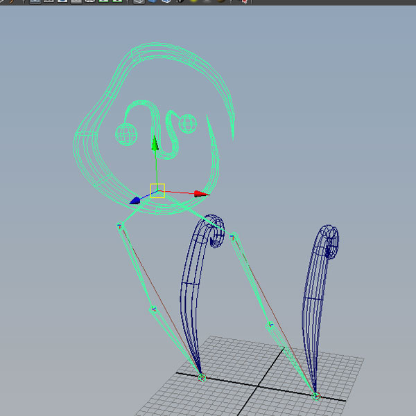
Notice the entire chain and the IK handles have been copied.
Finally, Select Foot_Handle_L and Foor_Handle_R and in the attribute editor open the IK Handle Attribute section and change Stickiness from off to sticky.
We can directly parent geometry to a joint. Select head_grp (under figure_grp) and then select head_jnt. Use the p hotkey to parent: Then move the head_jnt:
ctrl-Z to return to original position.
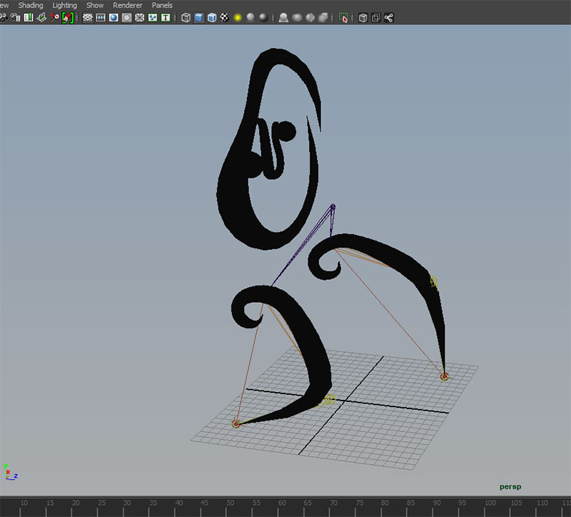
The head_grp geometry will not deform. We will want the leg geometries to deform with their joint chains. Select Hip_R and Leg_R (under figure_grp) and use:
Skin->Bind Skin->Smooth Bind
repeat with the left leg.
====================================================================
To create a walk cycle for this example, we will key three objects...the Head_jnt, Foot_Handle_L and Foot_Handle_R. Unlike the previous example, the feet and head will only move forward and we will use Curves->Post Infinity->Cycle with Offset to cumulatively increase their progress in the translate Z direction.
At frame 1, key Foot_Handle_R.TZ = -9 and Foot_Handle_L.TZ to 9. Key Head_Jnt.TZ to 0.
A half step will be the difference between the two feet which is 18 units. A full step will be twice that, or 36 units. So each step forward will advance 36 units over the previous value. Also, the Head_Jnt will need to increase 36 every 16 frames.
At Frame 1
Foot_Handle_L
t=1 ty = 0 tz = 9
t=9 ty = 0 tz = 9
t=13 ty = 5
t=17 ty = 0 tz = 45
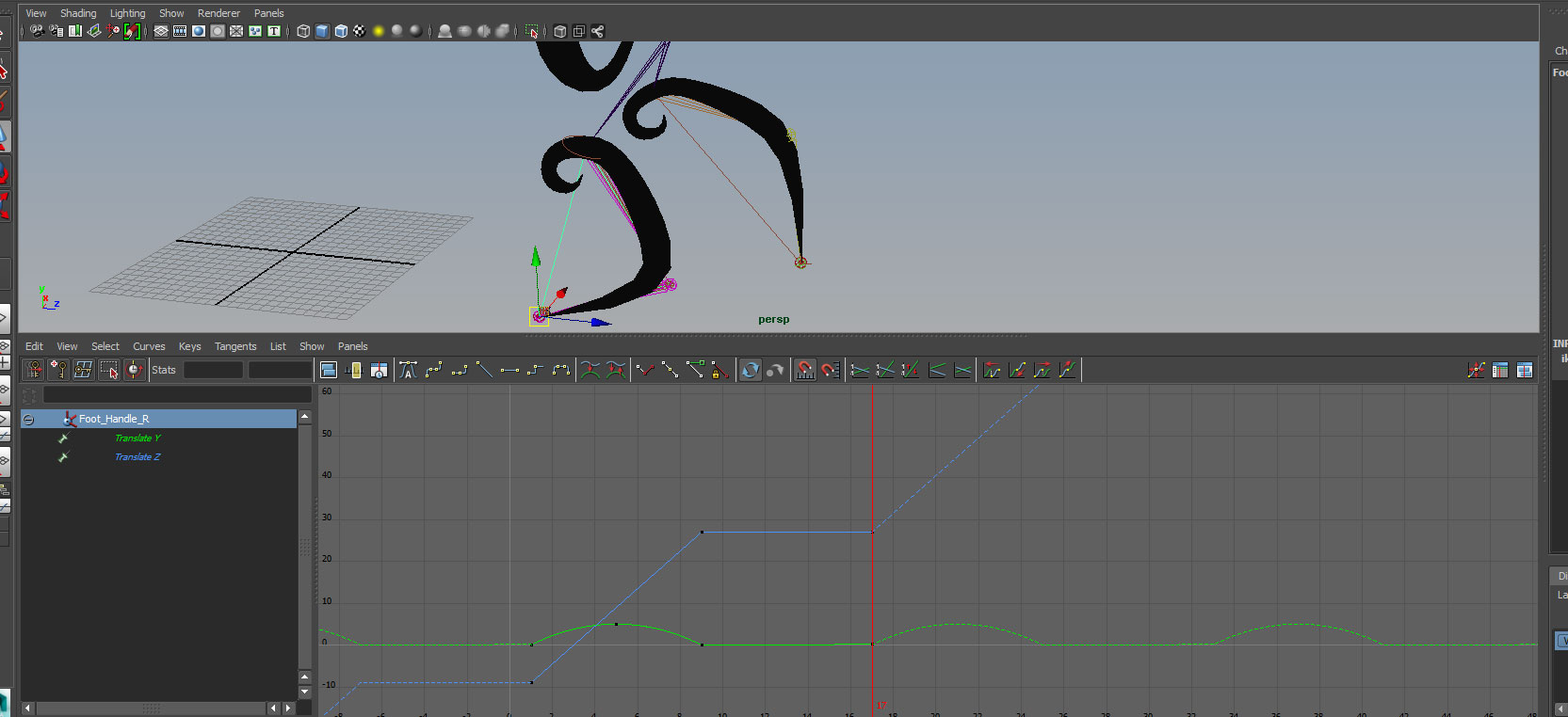
Foot_Handle_R
t=1 ty = 0 tz = -9 (minus 9)
t=5 ty = 5
t=9 ty = 0 tz = 27
t=17 ty = 0 tz = 27
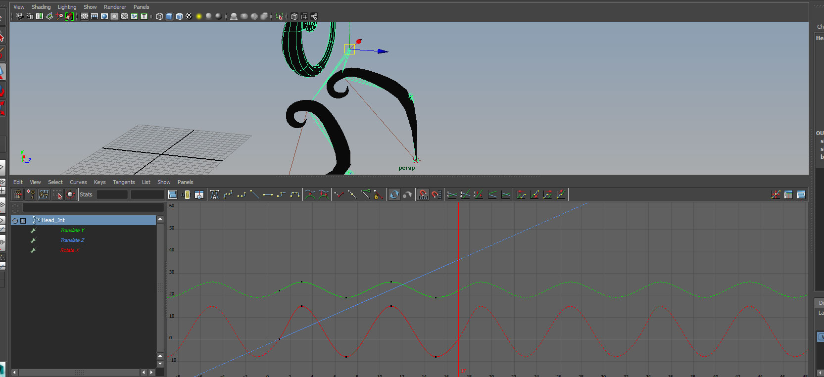
Head_Jnt
t=1 ty = 22 tz = 0 rx = 0
t=3 ty = 26 rx = 15
t=7 ty = 19 rx = -8
t=11 ty = 26 rx = 15
t=15 ty = 19 rx = -8
t=17 ty = 22 tz = 36 rx = 0
Make sure to turn on View->Infinity and use Curves->Post Infinity->Cycle with Offset and Linear Tangents for all translate Z curves, and regular cycle and spline tangents with all other curves.
Make sure to adjust tangents for translate Y Foot_Handle curves. Your final curves should look like this in the graph editor:
For Foot_Handle_L:

For Foot_Handle_R:
For Head_Jnt
Results are in the class folder examples\week_9\joints_end.ma